Jump to content


Photo
- - - - -

Getting a little frustrated with a floor system


  • Please log in to reply
4 replies to this topic

#1 Martin Livingston

Martin Livingston

    Advanced Member

  • Members
  • PipPipPip
  • 693 posts
  • LocationHalifax, Nova Scotia

Posted 14 February 2015 - 07:01 PM

I have spent most of today learning how to create a floor system  using a "real" construction project. The house has been designed with Autocad for our construction team and I am recreating it with Softplan.


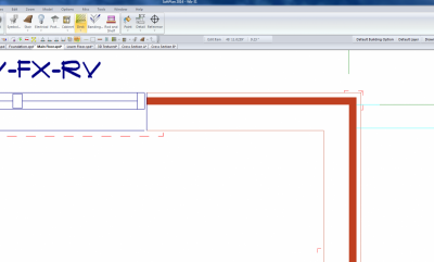
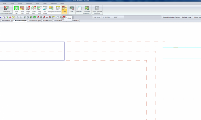
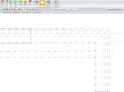
I am attaching three screen captures labeled "drawing mode", "floor system mode" and "with overlay". They all show the same corner of the house. Every time I try to create a floor the rim, joists and sheathing all snap to the middle reference line showing in the "floor system mode" picture. I cannot, for the life of me, figure out what this line represents. I have checked and double checked the wall assemblies above and below this floor system (it's a bungalow) and there are no materials located at that point. I have checked that the only bearing materials are the plates in the walls and none of them are in the wrong place (everything is lined up perfectly in the section drawings - except the rim board of course). I clicked the "trace line position"  and made sure every wall in the main floor and lower floor drawings indicated "outer most bearing". I have tried editing the location of the rim joist using "adjust and it just keeps snapping back to this unknown line.


There are two pale blue lines on the pictures that line up with the inside and outside edge of the studs wall. I added those to help determine what the unknown line  lines up with. It appears to be roughly in the center of the stud/plates.


Can anyone help me with this problem. I have run out of ideas. Everything I have read so far indicates that the floors should automatically snap to the outer most bearing. Just a quick note - floor system at the walls with brick veneer work just fine.

Attached Thumbnails

  • drawing mode.png
  • floor system mode.png
  • with overlay.png

Five out of four people are not very good with fractions

www.cresco.ca


#2 Thomas Roman

Thomas Roman

    Advanced Member

  • Members
  • PipPipPip
  • 341 posts
  • LocationSacramento, CA

Posted 14 February 2015 - 07:22 PM

perhaps send along a screen shot of the wall definition...


also, as a trouble-shoot, I would try to do a CHANGE WALL to swap out the exterior walls with a different wall... then see if the problem repeats... if not, then you'll know it's an issue with the wall definition...


#3 Chris Stewart

Chris Stewart

    Advanced Member

  • Banned
  • PipPipPip
  • 238 posts
  • LocationTexas

Posted 15 February 2015 - 08:04 AM

It would be easier for me if you would just send the drawing file.

I do not see any case where it would pick the middle of the wall.


My first suspect would be the wall definition.  


All comments are my opinion only and may or may not be correct
-Chris

#4 Martin Livingston

Martin Livingston

    Advanced Member

  • Members
  • PipPipPip
  • 693 posts
  • LocationHalifax, Nova Scotia

Posted 16 February 2015 - 01:22 PM

Mystery solved! I had turned off the "bearing" for the studs in the walls (leaving only the plates as bearing) not realizing that the software can only "see" what the Display Height reference line passes through. I reset the studs to bearing and everything works fine now.


Thanks for everybody's input.


Five out of four people are not very good with fractions

www.cresco.ca


#5 James Scales

James Scales

    Newbie

  • Members
  • Pip
  • 9 posts

Posted 17 February 2015 - 04:37 AM

Martin, super sleuthing and result sharing with others.


0 user(s) are reading this topic

0 members, 0 guests, 0 anonymous users