

Good Afternoon,
4 (hopefully) minor questions on my latest attempt to render...
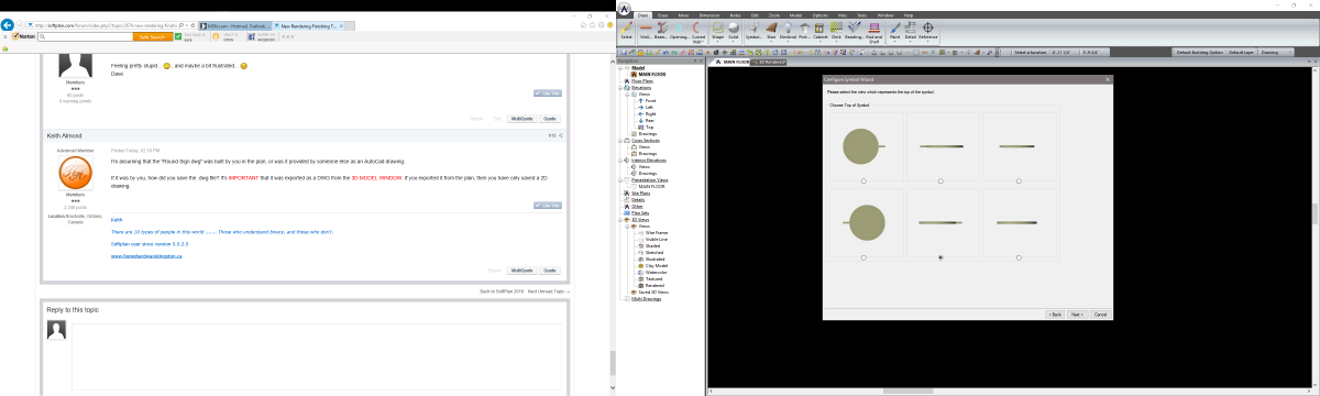
1. I wanted a custom door for the solid doors on the rendering. I drew what I wanted and started to save as a "Elevation Openings" in the system library. Once there, I found an opening that matched what I drew as shown on the screen capture. However, I can not select a door with that style. How do I use the door style already provided instead of creating a new one?
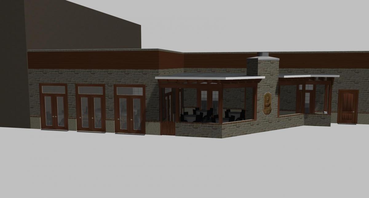
2. My roof over the patio section will not snap to the exterior of the fireplace, so I snap it to the interior and use a negative overhang. I think that is causing the white triangles where the roof and chimney meet. How can I force the roof to bear where I need it to?
3. I need to improve my skills working with shapes in 3d. Is there a tutorial somewhere? My task this time is to create a round sign hanging off the sides of the building. As close as I can come so far is the round hollow cylinder shown on the renderings.
4. How can I get the brick to show on the top of my kneewall?
Thank you for any assistance,
Dave


 , and maybe a bit frustrated...