Jump to content


Photo

Reference Points


  • Please log in to reply
11 replies to this topic

#1 Steve Pirtle

Steve Pirtle

    Advanced Member

  • Members
  • PipPipPip
  • 44 posts

Posted 06 March 2021 - 10:44 AM

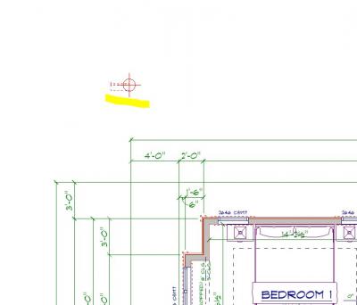
I have a customer that keeps making small modifications to the front elevation of the print I’m trying to finish up. It’s  generally not an issue but when I go to move the walls on the 1st floor and 2nd floor the two floors separate and are many ft apart. I narrowed it down to the reference points on the plan which are both on the walls to be moved. I have delegated them but the walls still are doing the same issue, if put back everything works back as before. Anyone had this issue before and how can I completely erase them and start over. I must also say this is on a multiple floor roof so maybe I’m putting them in the wrong place if need them at all. Thanks for any input.


#2 Joseph Smith

Joseph Smith

    Advanced Member

  • Members
  • PipPipPip
  • 824 posts
  • LocationWI

Posted 06 March 2021 - 12:33 PM

i use a chunk of phantom wall to the OUTSIDE of the building somewhere.  (phantom wall i mean; hidden, not printed or seen on the model 3d).  I can adjust anything on the levels just a long as i don't mess with the level common phantom wall that is used for the reference point.  Never did understand why SP recommends applying the reference point to an actual house wall.  My method is unaffected by reference point being accidently changed,..ie.  Pitching walls, level X,Y location or Z height changing and customer adjustments to the plan.


Try my method, you'll never go back.


  • Steve Haarmann and Gary Wicklund like this

Joseph A. Smith

http://granitedesigngroup.com


#3 Steve Pirtle

Steve Pirtle

    Advanced Member

  • Members
  • PipPipPip
  • 44 posts

Posted 07 March 2021 - 06:16 PM

Thanks Joseph I’m still a little vague on your system or method but it’s a lot better than the reference points. How do you define the levels to start with other than when he floors are stacked ?


#4 Chris Robinson

Chris Robinson

    Advanced Member

  • Members
  • PipPipPip
  • 72 posts
  • LocationKelowna, B.C. Canada

Posted 08 March 2021 - 02:14 AM

Wow Joseph. This advise could not have come at a better time. I just wish I would have read it hours ago. I have been struggling with floor heights when adding a floor system and I knew it was the reference point but didn't know how to fix it. The hidden wall reference point is great. I will use it for now on!


#5 Gary Wicklund

Gary Wicklund

    Advanced Member

  • Members
  • PipPipPip
  • 162 posts
  • LocationDuncan BC Canada

Posted 08 March 2021 - 08:14 AM

Thanks Joseph I’m still a little vague on your system or method but it’s a lot better than the reference points. How do you define the levels to start with other than when he floors are stacked ?

You’ll still need to use the reference point, circle one. 


you’ll need to get the hidden wall exactly in the same place on all your drawings since you already have the drawings done, you can use overlay to get things lined up.


#6 Gary Wicklund

Gary Wicklund

    Advanced Member

  • Members
  • PipPipPip
  • 162 posts
  • LocationDuncan BC Canada

Posted 08 March 2021 - 08:18 AM

i use a chunk of phantom wall to the OUTSIDE of the building somewhere.  (phantom wall i mean; hidden, not printed or seen on the model 3d).  I can adjust anything on the levels just a long as i don't mess with the level common phantom wall that is used for the reference point.  Never did understand why SP recommends applying the reference point to an actual house wall.  My method is unaffected by reference point being accidently changed,..ie.  Pitching walls, level X,Y location or Z height changing and customer adjustments to the plan.


Try my method, you'll never go back.

This is awesome, if I had a dollar for every time I had to re-Aline my reference point.   Lol


#7 Joseph Smith

Joseph Smith

    Advanced Member

  • Members
  • PipPipPip
  • 824 posts
  • LocationWI

Posted 08 March 2021 - 08:41 AM

Thanks Joseph I’m still a little vague on your system or method but it’s a lot better than the reference points. How do you define the levels to start with other than when he floors are stacked ?


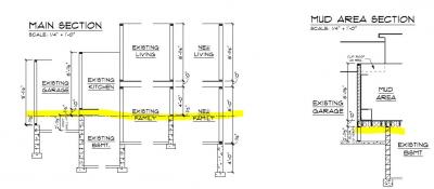
Hi Steve, the 'reference circle' is the most important one of the four, its the one i use 100% of the time.  it'll need to be associated to a wall as I've described earlier.  I'll be up to you to determine the proper offset and height of this wall.  if you have a complex tri-level or something with multi levels its a good idea to draw a quick line story section so you know exactly what height you make these phantom walls that house your reference circle.

Attached Thumbnails

  • Capture.JPG

Joseph A. Smith

http://granitedesigngroup.com


#8 James Holley

James Holley

    Advanced Member

  • Members
  • PipPipPip
  • 46 posts
  • LocationIndianapolis Metro, Indiana

Posted 08 March 2021 - 10:56 AM

There is one item I have found when working with reference points.

The need to be attached to the same wall positions on all floors, BUT, if you attach it in any location that "does NOT stay consistent) with the majority of walls per floor, it will do really odd things.
I found this the hard way as my garage top of wall on the main level or foundation level are not a the same elevation.

It may be because I design exactly as it's built and I have had several plans I had to find an interior point or an odd wall place, but I figured it out and works great now, all wall sections show just as drawn and built.


So, you have a raised main level ceiling with step up to living above. I draw my main wall at 12 or 12, I lower the offset appropriately on the upper level, but it didn't like that. It had to be on a wall on the main that was 10 foot tall then floor, then a upper wall that was 9 feet. The the plus and minus offset worked perfectly. I have one architect associate who ALWAYS lowers floor over garage down 2 feet. This is because they require 30" min. from grade to fin floor.


This is a render of one I fought for almost 2 days finding a good location as there are half a dozen or more wall ht differences and a couple stepped up areas on the upper, over raised lower ceilings.

FRONT COVER.jpg


  • Gary McKeon likes this

James L. Holley

SoftPlan user since 1993


"To explain the lure of speed you would have to explain human nature; but it is easier understood than explained...Speed is the second oldest animal craving in our nature..." -- T. E. Lawrence


#9 Joseph Smith

Joseph Smith

    Advanced Member

  • Members
  • PipPipPip
  • 824 posts
  • LocationWI

Posted 08 March 2021 - 02:04 PM

I never fight with plan heights, one of the first things I do as a designer is determine with simple lines, dimensions and text is my story height and any other heights involved....its key to not getting lost or confused with the vertical or X,Y changes as the project develops.  it makes no difference the complexity because you'll always know the main story height then deviations from that...ie  dropped garage walls with strange heights or whatever.


Again, keeping these phantom walls and reference points outside of the actual house will be unaffected by the development of the plan or customer changes.


Of course if you change a floor system from 11-7/8" I to 14" I you'll have to adjust the phantom offset...or if you walls go from 9' to 10' you'll have to adjust the phantom offset.


The attached image is a simple section that keeps everything in perspective and prevents you from going batty regardless of the number of levels


Attached Thumbnails

  • Capture.JPG

Joseph A. Smith

http://granitedesigngroup.com


#10 Brian Berzinskis

Brian Berzinskis

    Advanced Member

  • Members
  • PipPipPip
  • 470 posts
  • LocationNew Jersey

Posted 09 March 2021 - 09:12 PM

I actually actively try not to use reference points in the beginning when starting my drawings because I find that they tend to line up better especially so when I use the overlay command which I use a lot. I have found that when I use the reference points and dont pay attention to naturally lining them up, that even when just using overlay they seem to jump out of alignment from time to time and I have to turn off overlay and turn it back on for them to be in the correct position again.

#11 James Holley

James Holley

    Advanced Member

  • Members
  • PipPipPip
  • 46 posts
  • LocationIndianapolis Metro, Indiana

Posted 10 March 2021 - 05:12 PM

I never fight with plan heights, one of the first things I do as a designer is determine with simple lines, dimensions and text is my story height and any other heights involved....its key to not getting lost or confused with the vertical or X,Y changes as the project develops.  it makes no difference the complexity because you'll always know the main story height then deviations from that...ie  dropped garage walls with strange heights or whatever.


Again, keeping these phantom walls and reference points outside of the actual house will be unaffected by the development of the plan or customer changes.


Of course if you change a floor system from 11-7/8" I to 14" I you'll have to adjust the phantom offset...or if you walls go from 9' to 10' you'll have to adjust the phantom offset.


The attached image is a simple section that keeps everything in perspective and prevents you from going batty regardless of the number of levels

I used to do all sorts of crazy things like this, I only had issues if anything phantom accidentally got moved outside the print surface area and my title blocks were off paper.
By that time, chasing the item was a little annoying, SO, I just learned to pick a wall and use it, until at any point I find it to be off the off the referenced "Z", I just move them on the various floors. That render plan has 3 different height joists, AND they step up, then down, it was a challenge and it even has a non existent 3rd level , just for the roof and the additional height needed for knee walls sitting atop the Ceiling joists.
I end up with all 3 or 4 (as in this and many true Arch styles) floors and end up with them all in the same "Z plane heights" per floor then it's just adding and subtracting.
By this time I've had enough of them the plus minus offsets are burnt to memory. Kinda like fl to fl heights on all the different combinations of wall heights, for when drawing stairs and such.
Several years ago I would find all sorts of way to "trick or fool the system", but they have advanced it so far to the point I draw on one screen w/3D on the other and work from both screens to get my end result, like in the WAY past you could us a reference point on an elevation and it would align them, however with the newer versions, the horizontal lines always seem to match "unless a wall ht may have changed", but if you shorten or lengthen they no longer do line up left to right. I do a lot of multi draw overlays to get the new pieces in place properly, and eventually can erase existing and merge in new and a little clean up, I'm done.

My trick to never losing the placement would be to have it set to not extract the wall and place them all on a 0" tall wall in the middle of a large area like the garage. This is just me, the designs get pretty intense sometimes and little things can be forgotten. It's been working for me, and I've even learned how to get good TOPO's from Google and help guys with cut, fill and grade.11-12-20 REAR VIEW 1.jpg


  • Rick Kingsbury and David Zawadzki like this

James L. Holley

SoftPlan user since 1993


"To explain the lure of speed you would have to explain human nature; but it is easier understood than explained...Speed is the second oldest animal craving in our nature..." -- T. E. Lawrence


#12 Gary McKeon

Gary McKeon

    Advanced Member

  • Members
  • PipPipPip
  • 557 posts
  • LocationSilverton Oregon

Posted 10 March 2021 - 07:08 PM

Nicely done James!


0 user(s) are reading this topic

0 members, 0 guests, 0 anonymous users