Jump to content


Photo

New Foundation Wall w/ Brick Ledge


  • Please log in to reply
20 replies to this topic

#1 James Quesenberry

James Quesenberry

    Advanced Member

  • Members
  • PipPipPip
  • 126 posts
  • LocationSouth West Virginia

Posted 14 July 2015 - 03:16 PM

Hello Everyone,


I'd first like to say that this is my first post on the forum as I purchased SoftPlan in January but am now just getting a chance to go through the tutorials. So please be easy on me with this first question.


I have (3) issues that are plaguing me in trying to create a foundation wall.


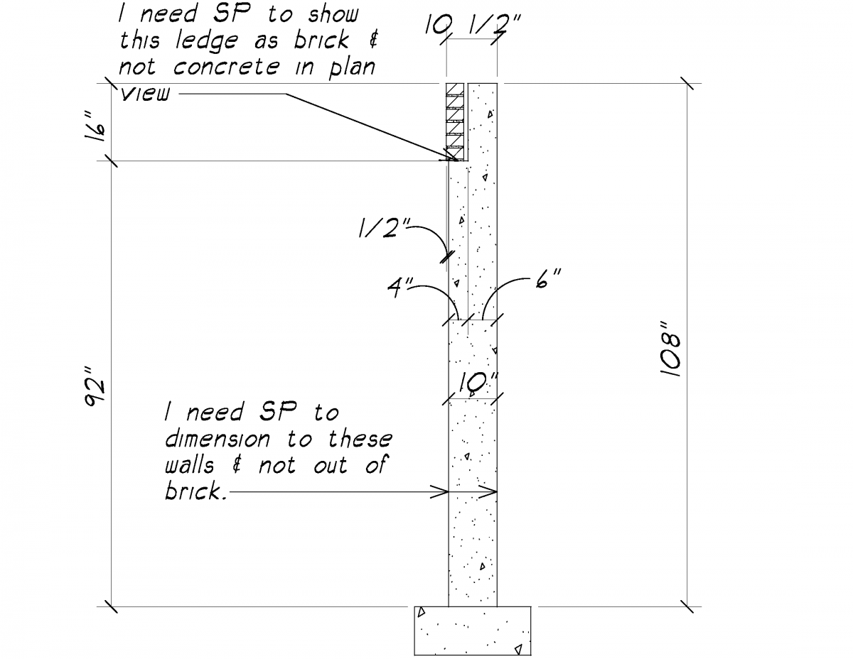
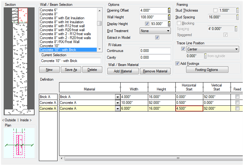
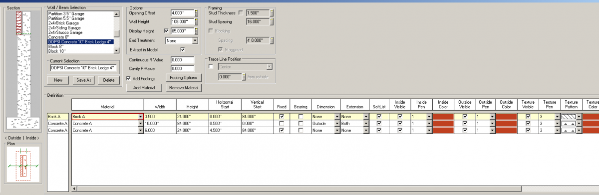
1) I am trying to create a 9'-0" tall 10" wide concrete foundation wall with a 16" deep 4" wide brick ledge. My problem is that I need the 3 1/2" wide brick to overhang the front of the foundation wall below by 1/2" to allow for a 1" airspace between the back of the brick and the 6" wide concrete ledge.


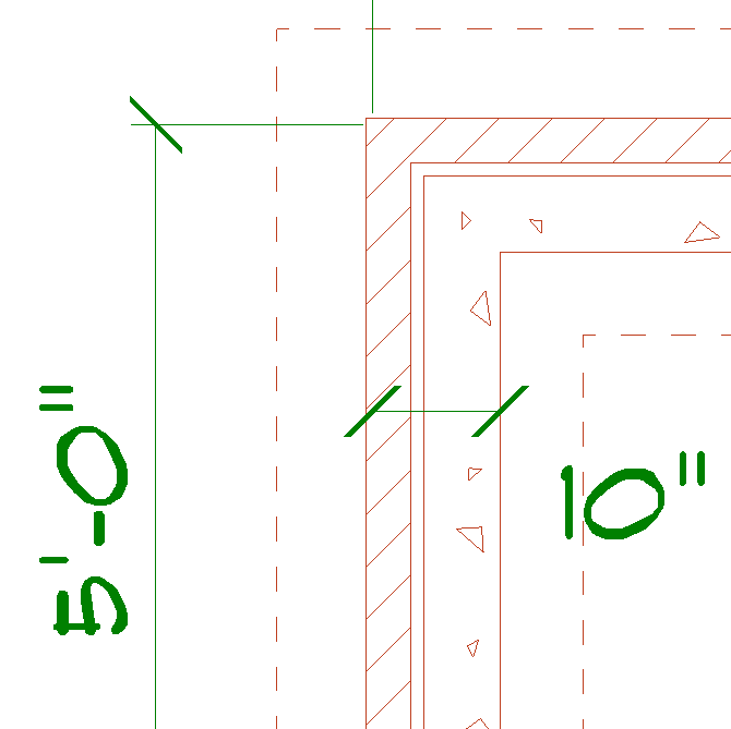
2) I need the foundation plan dimensions to dimension O.T.O of 10" wide concrete and not the 3 1/2" brick.


3) Wnen looked at in model view from the outside I'd like the foundation wall to look like all brick instead of 92" tall concrete with 16" tall brick above.


Would someone mind assisting me in creating this wall please?


Thank you,

Jerry Quesenberry


#2 Keith Almond

Keith Almond

    Advanced Member

  • Members
  • PipPipPip
  • 5,098 posts
  • LocationBrockville, Ontario, Canada

Posted 14 July 2015 - 06:34 PM

Jerry,


I'm having a little trouble actually understanding what you want in item one. Is it something like this?


Foundation Wall.png


The dimension can be any part of the wall you choose. You can select which material for the outside, which material for the inside or both.


The model view should really be what it is. If the wall is concrete, why do you want it to look like brick. Although you can copy and paste any finish you want onto any material.


Keith

There are 10 types of people in this world ....... Those who understand binary, and those who don't.

Softplan user since version 5.5.2.5

www.homehardwarekingston.ca

#3 James Quesenberry

James Quesenberry

    Advanced Member

  • Members
  • PipPipPip
  • 126 posts
  • LocationSouth West Virginia

Posted 15 July 2015 - 08:36 AM

Thank you for taking the time to respond Keith. In trying to be detailed enough in my info I think I made things worse. Plus it didn't help that I didn't know how to attach a file to my post. Here is an image of what I am looking for. After thinking about it Keith how do I make the 4" ledge look like brick in plan view instead of concrete?


Thank you,

Jerry Quesenberry

Attached Thumbnails

  • FNDWALL.png


#4 Keith Almond

Keith Almond

    Advanced Member

  • Members
  • PipPipPip
  • 5,098 posts
  • LocationBrockville, Ontario, Canada

Posted 15 July 2015 - 10:45 AM

You would design the wall exactly like that in Softplan's wall definitions menu. So a 10" wall - 92" high with 16" high brick wall above and a 16" high 6" concrete wall above. And adjust the display height to suit (to more than 92"). You'll have a horizontal start of 0.5" on the 10" concrete, and a horizontal start of 0" on the brick above.

Attached Thumbnails

  • 2015.07.15_12h43m36s_001.png

Keith

There are 10 types of people in this world ....... Those who understand binary, and those who don't.

Softplan user since version 5.5.2.5

www.homehardwarekingston.ca

#5 Keith Almond

Keith Almond

    Advanced Member

  • Members
  • PipPipPip
  • 5,098 posts
  • LocationBrockville, Ontario, Canada

Posted 15 July 2015 - 01:11 PM

Should end up looking something like this .... You'll notice the plan view change as you increase the display height.

Attached Thumbnails

  • 2015.07.15_15h10m20s_001.png

Keith

There are 10 types of people in this world ....... Those who understand binary, and those who don't.

Softplan user since version 5.5.2.5

www.homehardwarekingston.ca

#6 James Quesenberry

James Quesenberry

    Advanced Member

  • Members
  • PipPipPip
  • 126 posts
  • LocationSouth West Virginia

Posted 16 July 2015 - 07:01 AM

Hey Keith,


I have created exactly what you have. Is it possible though to show this in plan view but force SP to dimension to the outside of the concrete below the display height?


Thank you,


#7 Keith Almond

Keith Almond

    Advanced Member

  • Members
  • PipPipPip
  • 5,098 posts
  • LocationBrockville, Ontario, Canada

Posted 16 July 2015 - 07:18 AM

Softplan only dimensions where you ask it too. In my example, I chose the dimension and extension as BOTH for the 10" concrete (you can almost see it in the plan).


You can choose INSIDE, OUTSIDE or BOTH for any of the wall materials. However you can only have one dimension for the wall, no matter what you choose (unless that's changed for 2016 - haven't tried it recently). You cannot dimension each material.


Keith

There are 10 types of people in this world ....... Those who understand binary, and those who don't.

Softplan user since version 5.5.2.5

www.homehardwarekingston.ca

#8 randolph cohn

randolph cohn

    Advanced Member

  • Members
  • PipPipPip
  • 869 posts
  • Locationmarin county - california

Posted 16 July 2015 - 08:19 PM

you can always add a "line/paint break" (it's a line that won't print)

and dimension to that,  can put in as many as you want.


randy

v10 to future 2016+ ;)


#9 Keith Almond

Keith Almond

    Advanced Member

  • Members
  • PipPipPip
  • 5,098 posts
  • LocationBrockville, Ontario, Canada

Posted 16 July 2015 - 08:41 PM

Can you clarify that Randy.


Do you mean add a "line/paint break" into the wall definition?


I have to admit, I'm not following you here.


Keith

There are 10 types of people in this world ....... Those who understand binary, and those who don't.

Softplan user since version 5.5.2.5

www.homehardwarekingston.ca

#10 randolph cohn

randolph cohn

    Advanced Member

  • Members
  • PipPipPip
  • 869 posts
  • Locationmarin county - california

Posted 17 July 2015 - 01:31 PM

i just suggested to add a "line/paint breaks" where you wanted

to dimension in a wall.

that you couldn't do with the way you have the wall definition set up.


it is a little confusing the way i'm explaining it but you should be used

to that by now.


randy

v10 to future 2016+ ;)


#11 James Quesenberry

James Quesenberry

    Advanced Member

  • Members
  • PipPipPip
  • 126 posts
  • LocationSouth West Virginia

Posted 20 July 2015 - 10:22 AM

Hey Keith,


I have tried what you have said. But when the display height is set as you have suggested I can't get it to dimension out to out of concrete as SP wants to dimension out to out of brick automatically. This happens even though I selected the "none" option for dim & ext for the brick material & the "both" option for dim & ext for the concrete material below, The only way to get it to dimension out to out of concrete is to change the display height to where it actually is in the concrete below. My newbie thoughts (Which I'm sure don't account for much since I'm the one with the question.) would be that Randy is correct. You would need to draw a phantom line of some sort a 1/2" in from out of brick to have it dimension & look correct.


I do find it kind of strange that SP does not come with a standard concrete wall w/ brick ledge that matches the standard 2x4/Brick wall in the program.


Thank you,

Jerry

Attached Thumbnails

  • FND WALL.png


#12 Keith Almond

Keith Almond

    Advanced Member

  • Members
  • PipPipPip
  • 5,098 posts
  • LocationBrockville, Ontario, Canada

Posted 20 July 2015 - 10:43 AM

To be honest, I have never tried to dimension something that wasn't on view, but it surprised me that it doesn't do what was asked of it. Maybe this is something you should bring to Tech Support's notice.


With regard to the standard walls, there are so many regional construction methods, and so many possible variants that no matter what they added, someone would want something else. They also make it so easy to customize walls that you can easily design exactly what you want.


Keith

There are 10 types of people in this world ....... Those who understand binary, and those who don't.

Softplan user since version 5.5.2.5

www.homehardwarekingston.ca

#13 Todd Williard

Todd Williard

    Advanced Member

  • Members
  • PipPipPip
  • 191 posts
  • LocationPA

Posted 20 July 2015 - 01:01 PM

Just a thought, but could you add a "NONE" material at 0" horiz. and heightfrom bottom to the top of the wall and dimension to the inside of that?


  • Keith Almond likes this

V11-V2024


#14 Keith Almond

Keith Almond

    Advanced Member

  • Members
  • PipPipPip
  • 5,098 posts
  • LocationBrockville, Ontario, Canada

Posted 20 July 2015 - 03:17 PM

Actually ... Good thought a NONE (with NO VISIBILITY) material at 0.5" embedded 0.5" into the brickwork might do it - It's the concrete he wants to dimension. Good thought Todd


Keith

There are 10 types of people in this world ....... Those who understand binary, and those who don't.

Softplan user since version 5.5.2.5

www.homehardwarekingston.ca

#15 James Quesenberry

James Quesenberry

    Advanced Member

  • Members
  • PipPipPip
  • 126 posts
  • LocationSouth West Virginia

Posted 20 July 2015 - 08:15 PM

Thanks again for everyone chipping in here and sorry to be ignorant. I understand the none material but when you say "at 0.5"" I'm assuming you mean a horizontal start of 0.5 or is it a vertical start? I also do not understand "embedded 0.5""? Another question I have is how does adding another material accomplish this when changing all of the dims & ext. to none, other than the 10" concrete wall, won't?


Thank you 

Jerry


#16 Keith Almond

Keith Almond

    Advanced Member

  • Members
  • PipPipPip
  • 5,098 posts
  • LocationBrockville, Ontario, Canada

Posted 20 July 2015 - 08:50 PM

I'm,not at a Softplan machine at the moment, or I would test this concept for you.


Yes 0.5" horizontal start. That brings it in line with the outer edge of the concrete wall below. By embedded in the brick, I mean with the same vertical start and height as the brick, but 0.5" into it. That way the NONE material is across the display height, on the same line as the outer face of the concrete wall below.


We have already (apparently) established that the dimensions don't work for anything outside the display height, so set the dimension and extension to the outer face of the "NONE" material, and the inner face of the top concrete portion of the wall.


This wall the NONE material takes the place of the "phantom" line that Randy suggested earlier. With visibility turned off it shouldn't show on plan but MAY work to control the dimensions.


I say MAY, it's possible that with no visibility it may not work for the same reason that the outer face of the lower concrete wall doesn't work. However, give it a try, what's the worst that can happen.


Keith

There are 10 types of people in this world ....... Those who understand binary, and those who don't.

Softplan user since version 5.5.2.5

www.homehardwarekingston.ca

#17 Keith Almond

Keith Almond

    Advanced Member

  • Members
  • PipPipPip
  • 5,098 posts
  • LocationBrockville, Ontario, Canada

Posted 20 July 2015 - 08:56 PM

Let's go back to post #11 for a minute ....


Before you do anything else, You have extension set to BOTH, but only have OUTSIDE set for dimension .... Try setting dimension to BOTH for the 10" concrete wall, and try again. You can't dimension between only one point. Should have looked more closely at that earlier, instead of just reading the text.


NEVER MIND: No matter what you do, the dimensions will only work on what is detailed at the display height. As you change the display height then the dimension changes to suit.


If you put in the NONE material as detailed above, that will work ... just tried it.

Attached Thumbnails

  • 2015.07.21_08h33m33s_001.png
  • 2015.07.21_08h34m41s_002.png

Keith

There are 10 types of people in this world ....... Those who understand binary, and those who don't.

Softplan user since version 5.5.2.5

www.homehardwarekingston.ca

#18 James Quesenberry

James Quesenberry

    Advanced Member

  • Members
  • PipPipPip
  • 126 posts
  • LocationSouth West Virginia

Posted 21 July 2015 - 07:21 AM

Good morning,


I did go back and set dims & exts to "both"  for the lower concrete wall with no effect. The none material did do the trick. So from this point forward I will have to remember that the dims & exts are impacted by the display height. Would that be correct?


If you folks would also take a look at my finished wall and see if anything else needs to be corrected, I would appreciate it.


Thank all of you for your assistance.


Jerry


Attached Thumbnails

  • FndWallBrckLdg.png
  • FndWallBrckLdg3D.png
  • FndWallBrckLdgPln.png


#19 Keith Almond

Keith Almond

    Advanced Member

  • Members
  • PipPipPip
  • 5,098 posts
  • LocationBrockville, Ontario, Canada

Posted 21 July 2015 - 08:17 AM

.... I will have to remember that the dims & exts are impacted by the display height. Would that be correct?


That would seem to be correct.


The wall looks good James. The only thing I would have done differently, would be to set the NONE material to 0" thick and set the dimensions and extensions to OUTSIDE of the NONE and INSIDE of the 6" CONCRETE, but I don't think that will make any difference.


If you are going to build this wall with a frost wall, I would detail the frost wall with it. That way the windows cut through correctly, without having to add blank openings. BUT again, that's just my preference.


Keith

There are 10 types of people in this world ....... Those who understand binary, and those who don't.

Softplan user since version 5.5.2.5

www.homehardwarekingston.ca

#20 James Quesenberry

James Quesenberry

    Advanced Member

  • Members
  • PipPipPip
  • 126 posts
  • LocationSouth West Virginia

Posted 22 July 2015 - 10:50 AM

This may be typical of SP walls in general but being new this is the first time I've seen it in my training. The upper concrete wall w/ brick veneer ledge that everyone helped me create cleaned up nicely against the standard 10" concrete wall but it didn't work out so well at the intersection below as the brick continued thru. Any thoughts on what to do here?


Thank you,

Jerry


BRK LGE ISSUE.png


0 user(s) are reading this topic

0 members, 0 guests, 0 anonymous users