First, thanks to Keith for putting me on to the method used in his posts responding to my original cry for help. I had never used roof planes before, or roof edge profile for that matter, so I had to mess around with them a bit just to get the basics. I made his comment "may need a little bit of playing" the understatement of the year, for this particular project and here is why.
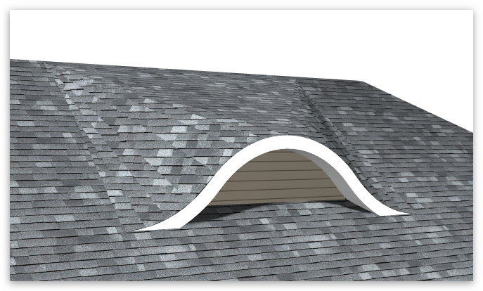
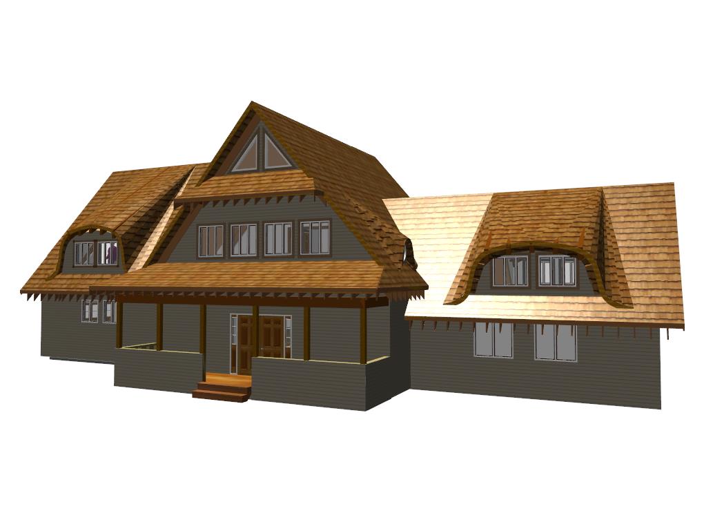
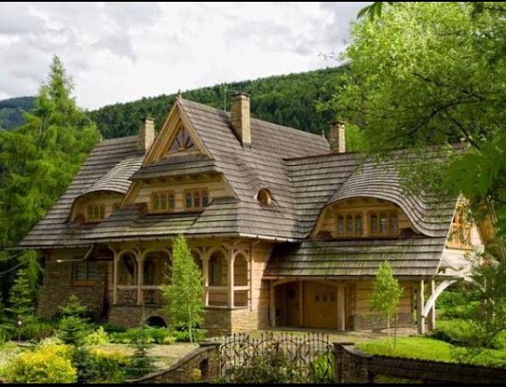
Let me set the table for anyone who wants to play along. "Eccentric" client gives me the photo of the house in post #1, and says "I want THAT house on the outside, with some changes to the floor plan within. The basic structure is a basic rectangle, gable end roof, with a perpendicular rectangular structure intersecting on each side. The right side changes from garage to living room with vaulted ceiling. The left side becomes garage with living space above, and all dormers to be as exact as possible to photo, and back-to-back. (#85 snow load, btw.) So for me, step #1 meant figuring out main roof pitch, and also size of windows in the photo, as everything begins with them. I came up with a 14/12 pitch on main structures, (dormer pitches tbd) and windows are (2) 3'6" x 3'0" window units with 3 sections. Think I am close?
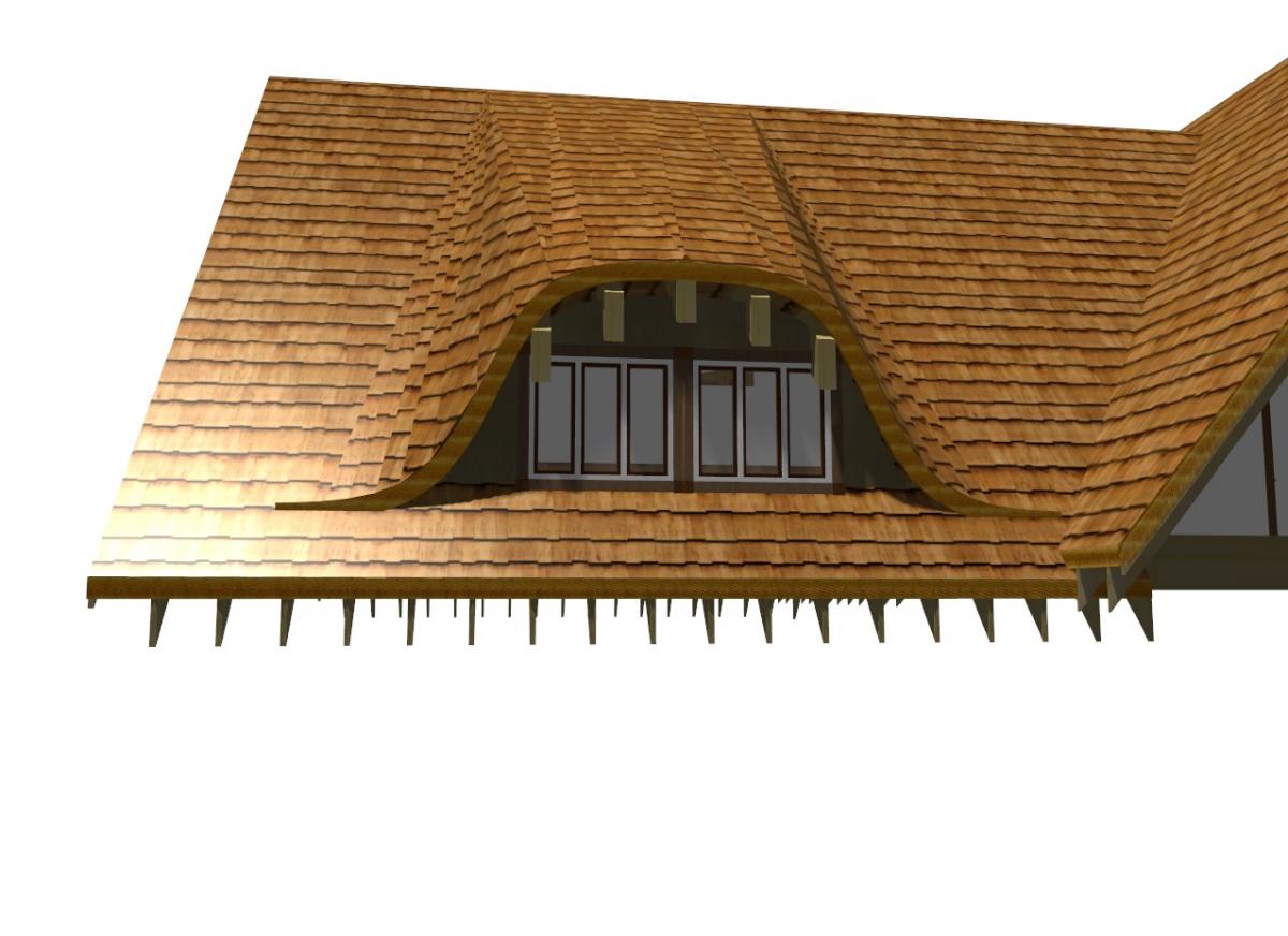
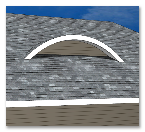
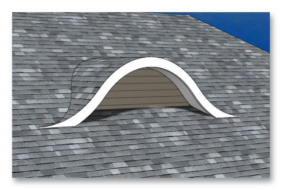
Step #2 is to draw the dormer and place the windows, so that I can work out the roof structure support. When I first looked at the photo, I planned on drawing a simple shed dormer, square edges inside and out, and then overbuilding the curves on top of that, which would work and be the least expensive method, but if you look close, that is not how those were built. There are 5 beam ends overhanging, looks like 1 ft. One in the center, (high point) one at outside edge of window each side, and one midway between them. From what I could see in the photo, my best guess was a 1' difference in elevation from outside to inside, instead of a flat section in the middle, like in my first attempt, and that is what made the roof edge profile method so #$#*@ difficult. Further explanation to come. The difference can be seen here. The NW dormer has that flat center section, while the others have the slight peak in the center.
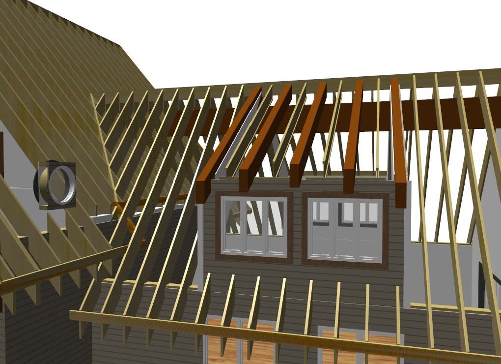
My final decision is to build the dormer roof using those beams, with intermediate rafters that will actually form the curve, with a "built on roof" wall forming the edge for the inside view of sidewalls. The exterior curve outside of the sidewalls will be overbuild on main roof using hand crafted site-built rafters with curve cut in. Pity the framer.
Before I continue, a few tips. I very much design in 3d mode, after all, why not? Warning: crunching a lot of data by the time you get very far, so your computer will at some point choke. You need a fast processor with lots of ram, and even then expect problems. As I got to the end, when I would click on a tool in the toolbar, it would switch to "measure distance" no matter which tool I had picked. At that point, I would hit save, and shut down softplan to cool down and reboot.
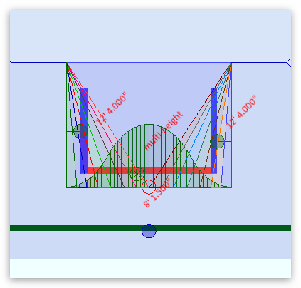
Also, roofs in general can be very complex, and it is critical to be as precise as possible with every thing that you draw. It is vital that every reference point actually reference the correct part. Even then, on many occasions, I would make and adjustment to one edge of the dormer, like "heel height" and get a different result when entering the exact same info to the other edge. That makes it impossible to know whether you have made a mistake, or whether the program has gotten confused. Remember, we are creating a close facsimile of a shed roof with compound curved edges using tools available, which are not able to do it with 1 click.
In the "more than one way to skin a cat" scenario, (sharp eyes will have already noticed the SE dormer in fig 0) you can be working on a different type roof and achieve similar results, but the actual process my be slightly different. The key is to check the result of every click before proceeding, as you get more comfortable with the process.
Step 1: build main structure walls 20'x24' in this case, (2x6 plate in this case since it is a first floor vaulted roof). Go into drawing options, set roof pitch to 14", rafter size to 11.875", and heel height to 12". Trace roof, edit ends to gable, plain gable corners, no soffit, auto stick frame. Generate a 3d textured image. Go to materials and uncheck whatever roof material you have so you can see the framing.
Sadly, dinner is ready, so I will continue this later, where we will actually get to drawing.


 If I try making a solid, I will post result. I imagine that it will be representative, but not something that will look great in 3d.